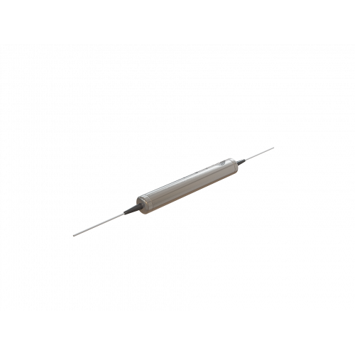
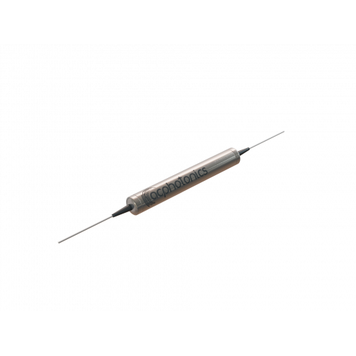
High Power Telecom Wavelength PM Isolator
Features
- High Isolation
- High Isolation
- High Return Loss
- High Return Loss
- Epoxy Free Optical Path
Applications
- Fiberoptic Amplifiers
- CATV Fiberoptic Links
- Fiberoptic Systems Testing
- Fiberoptic LAN Systems
- Telecommunications
Specifications
| Parameter | Unit | Specifications | |||
|---|---|---|---|---|---|
| Operating Center Wavelength (λc) | nm | 1310,1550,1585 or Custom | |||
| Stage | Single | Dual | |||
| Grade | P | A | P | A | |
| Typical Peak Isolation | dB | 42 | 40 | 58 | 55 |
| Minimum Isolation* | dB | ≥ 30 | ≥ 28 | ≥ 46 | ≥ 45 |
| Typical Insertion Loss** | dB | 0.40 | 0.50 | 0.50 | 0.70 |
| Insertion Loss*** | dB | ≤ 0.60 | ≤ 0.70 | ≤ 0.70 | ≤ 0.90 |
| Return Loss (In/Out) | ≥ 55/50 | ||||
| Extinction Ratio | dB | ≥ 20 | ≥ 18 | ≥ 20 | ≥ 18 |
| Average Optical Power | W | ≤ 1, 3, 5 and 10 | |||
| Peak Optical Power for ns Pulse | kW | ≤ 10 | |||
| Tensile Load (Max.) | N | ≤ 5 | |||
| Fiber Type | PM Panda fiber or Custom | ||||
| Operating Temperature | °C | - 5 to +70 | |||
| Storage Temperature | °C | -40 to +85 | |||
| Package Type | Standard | ||||
| Package Dimensions | mm |
A=Ø5.5 x L35 (Optical power: ≤ 5W) Ø6.0 x L48 (Optical power: 6 - 10W) |
|||
Note:
* λc ± 10 nm, 23 ℃, all polarization states.
** λc ± 20 nm, 23 ℃, all polarization states.
*** λc ± 20 nm, all temperature, all polarization state.
1. IL is 0.3 dB higher, RL is 5 dB lower, and ER is 2 dB lower for each connector added. Connector key is aligned to slow axis.
2. The Optical Power is 1W only for connector added.


